|
|
| HOMEPAGE | VEHICLE HISTORY | TECH SPECS | FOR SALE & WANTED | MY VAN | TECHNICAL GUIDES |
My Vans I'm always on the lookout for more Bedford Rascal vans in particular - see here. |
I picked up the replacement G16 engine on the 24th of March and began to work on it shortly after. This engine came from a 1999 Suzuki Baleno 1.6i - it should develop 95BHP which should be considerably faster than the original 59BHP engine! I started by mating up the engine to the Suzuki Carry gearbox. This involved drilling out the top two bolt holes in the gearbox to 12mm. The G16 uses M12 bolts to attach the gearbox while the original G13 only used M10 bolts.
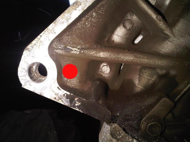
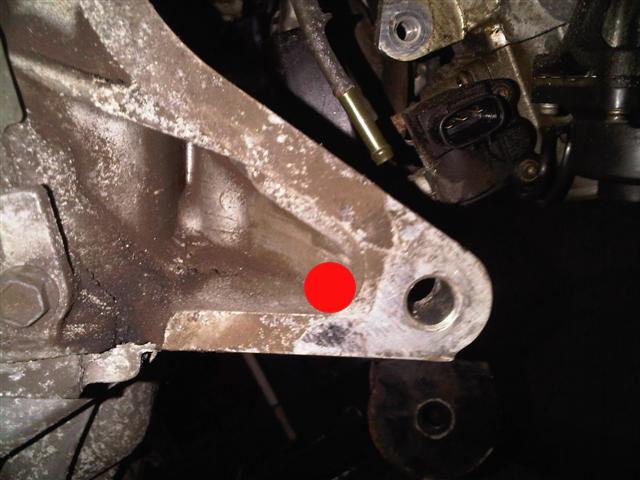
Only the top two bolt holes line up with the engine. The lower two holes are about 2cm inboard towards the engine block and will need some modification to get the gearbox to bolt to the engine in that position. I have a plan though on how I'm going to sort this out but I'll detail this later on. The photos below show what I mean - the red circles are roughly where the bolt holes are on the G13B gearbox. I don't think there's enough metal there to drill and tap into so I think what I will do is create a metal plate with an M10 bolt on one side and the M12 bolt on the other to "bridge the gap".
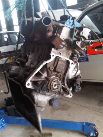
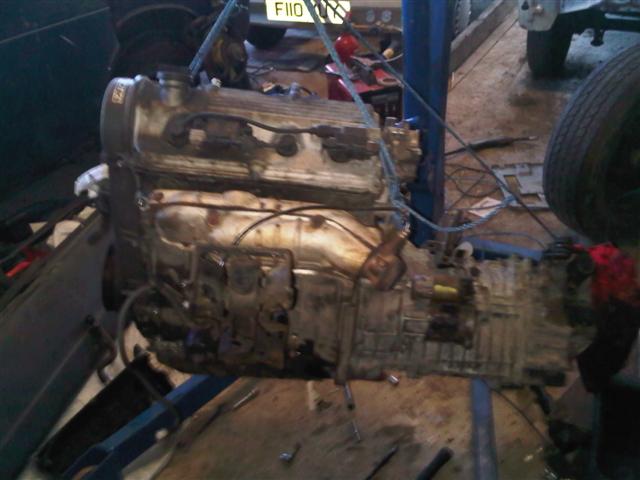
The above photo shows the original Carry inlet manifold and throttle body now (temporarily) bolted to the G16B engine. I was extremely surprised at how this went together and it also meant that I can use the alternator that came with the G16B because I didn't get one with the van itself. I have ordered new inlet and exhaust manifold gaskets so both these manifolds will be torqued into position when these arrive.
I was also extremely surprised to find that the angled sump bracket from the original G13B engine bolts right onto the new engine. You can see just how much of an angle the engine sits at when it's installed in the van. I had been under the impression that the sump was going to need modification to clear the big end bearings but they don't seem to be sticking down any further in the G16 engine than they did in the G13. Anyway - that's all for now. Just waiting on the flywheel to arrive so that I can align the gearbox properly and sort out the lower mouting points.
Update: 31st March 2011
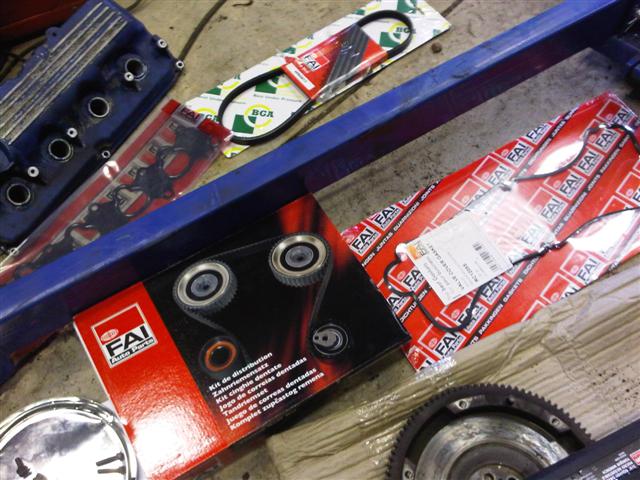
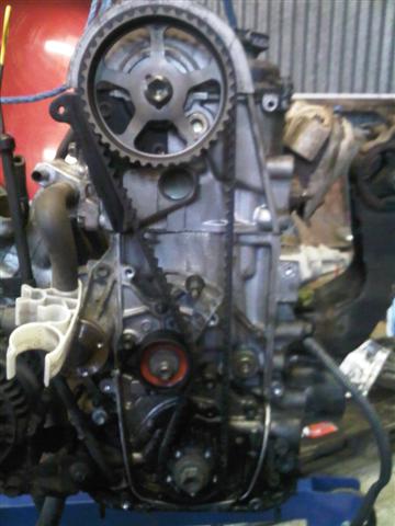
A whole load of new parts arrived earlier this week for the engine. I ordered a new timing belt kit because I didn't know when the belt was last changed and since the engine is out of the van it makes sense to change it. Here's a shot of the engine with the new timing belt installed:
It's a very simple job - I usually shy away from working with the timing belt. I hate them. But this engine was very simple. All you need to do is line the stamped in letter "E" on the top pulley with the groove in the cam cover and the punched mark in the lower pulley with the arrow directly above it. Modifications required to install a G16b into a Suzuki carry:
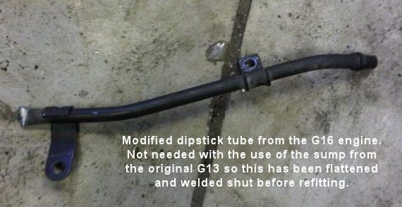
Dipstick Modification
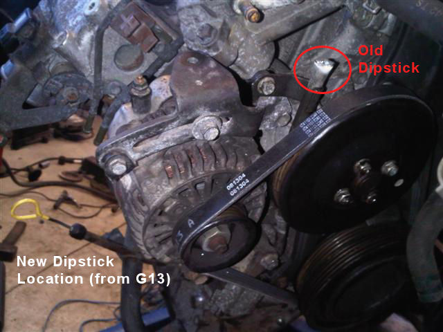
I thought about how I was going to plug the hole for the original dipstick that came with the G16B engine for a few days but I eventually decided to just plug the pipe and reinstall it. I did this by flattening the end with a hammer and them welding it permenantly closed before refitting it to the engine. Because of the angle the engine sits at in the Carry van this won't cause a problem because there isn't really any way in which the oil can even get back up the tube. In the photo below you can see where the new dipstick is located - this is the original dipstick from the G13B engine and it mounts to the angled sump. When the engine is installed in the van this dipstick will be near enough vertical.
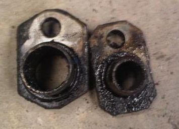
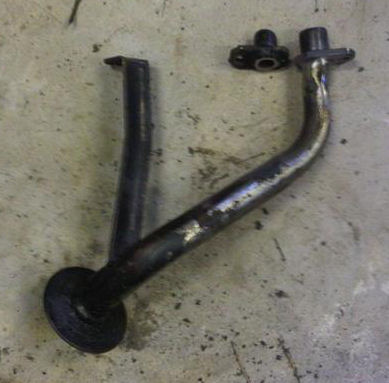
Oil pickup pipe modification *** This is a critical modification *** - Failure to do this will result in no oil pressure The oil pickup pipe from the G13B has a smaller bore than the one from the G16B. However, the G16B pickup can't be used because of the angle of the sump. What you need to do is remove the tip from the G16B oil pickup pipe and weld it onto the end of the pickup pipe from the G13B. The photo below shows the difference in size between the two pickup pipe ends. The G16B is on the left and the G13B is on the right. You can clearly see the difference in the bore of the pipe.
Below is the finished oil pickup pipe. I decided to cut the pipes above the flat metal plate so that the seal it makes when you install it isn't effected in anyway. You could cut it below the flat plate in theory but you would need to weld it very carefully to acheive a perfect circle again. There is a rubber o-ring that goes around the end of the pipe between the flat plate and the engine block. I removed this o-ring before welding the pipe just to make sure it wasn't damaged.
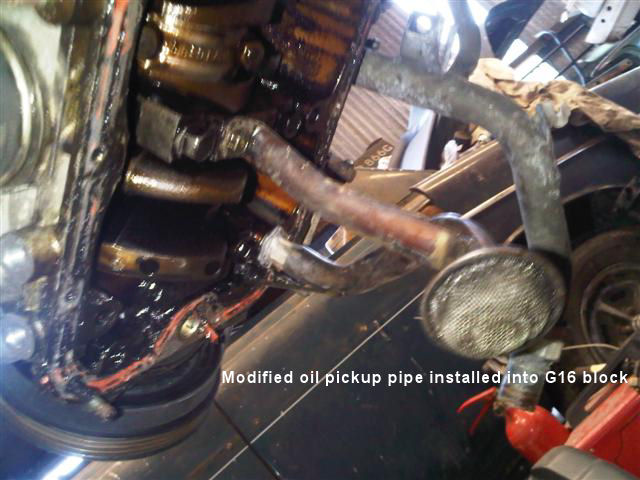
And the oil pickup pipe installed in the engine:
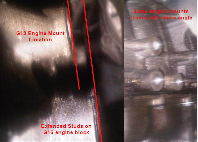
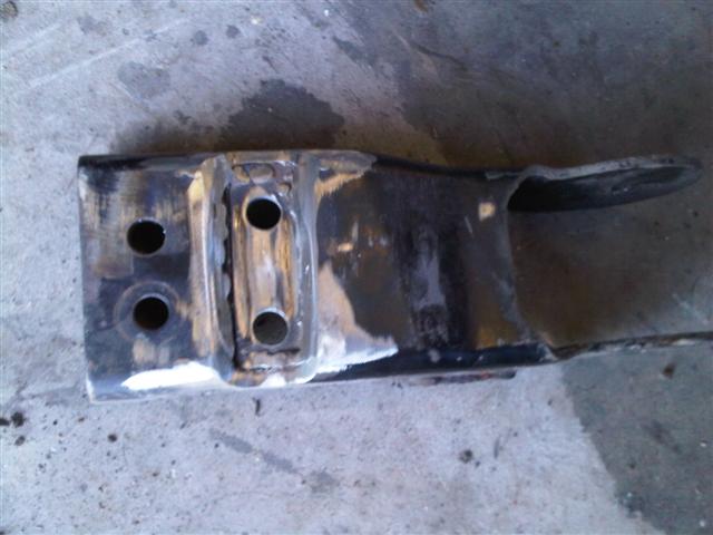
You can see above that the support leg from the oil pickup pipe is bolted into the third main bearing cap. This was the same position on the G13B engine and did not require any modification. TIP: Bolt the end of the oil pickup pipe to the engine and tack it in place on the end of the oil pickup pipe to ensure that you get the bolt hole lined up correctly. Otherwise it could be a major pain getting the whole thing lined up properly. This is a critical job to ensure that the oil can be picked up properly from the angled sump of the engine. It took me quite some time to do this and get it right - don't rush it! Problems encountered: The driver's side engine mount is going to be an issue on the G16B block because the studs that it bolts to stick out about 5mm further than those from the G13B block. You can see below the three stud holes that the engine mount bolts to - the lower two studs stick out too far which means that the top one will either need packed out with washers or the engine mount will need to be modified. I haven't decided what route I'm going down with this one so stay tuned for the next update.
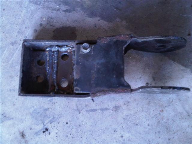
Update 7th April 2011 I spent today getting the engine and gearbox ready for installation in the van. My first task was to modify the engine mount to address the problem highlighted above. I measured the depth of the holes in the block because I thought that I would just be able to file them down level with the top hole but this wasn't the case - they are the same depth. What I did was cut a section out of the engine mount and then recessed it to allow for the extended studs - see the photos below: TIP: Modify the engine mount before installing the intake manifold - it would make access a lot easier!!
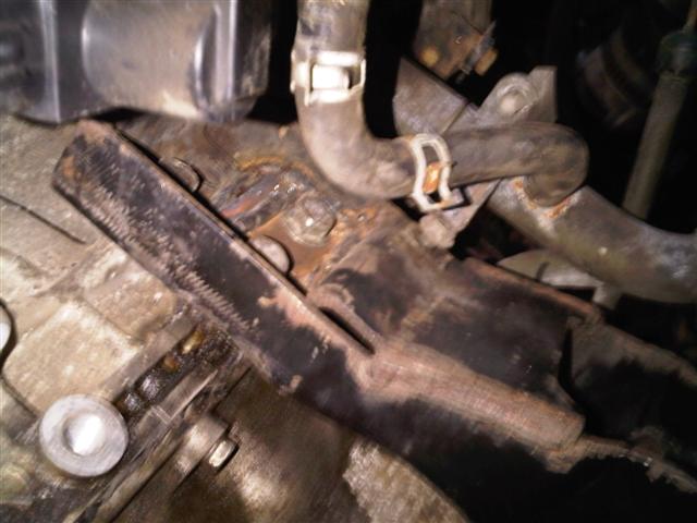
You can see in the photo below how the lower two holes have been "recessed" into the engine mount to allow for the additional 5-6mm in the length of the mounting points on the engine.
And this is the engine mount installed on the engine:
By modifying the engine mount itself this will mean that the engine will sit in the exact same position as the original G13B engine. I could have simply packed out the top hole with washers to take up the extra gap but then this would have meant the engine wouldn't sit where it was designed to and could have potentially put pressure on the gearbox/clutch etc. After I finished modifying the engine mount I turned my attention to the engine and mounted the clutch to the flywheel and then fitted the gearbox and starter motor. Essentially now the engine and gearbox are ready to be installed in the van.
I still have to secure the gearbox to the "wings" on the engine where the bolt holes don't line up and I also need to swap over the cam position sensor and housing from the original engine because this also looks to be different on the G16B. More soon...
|